- Introduction
- Building the lickometer
- Lickometer circuitry
- Lickometer in action
- Part 2: DIY water reward system
Introduction
Back To Top
Graduate school has taken me in some unexpected directions (like teaching a neuroscience course inside a prison), and one of those directions has been the measurement of how and when a mouse licks its tongue. That’s right. We train mice to indicate a decision about what texture they feel on their whiskers by licking a device called a “lickometer” or “lickport.” This information can be used to aid in the study of many different phenomena (I give a few examples below). There are several companies that sell these devices but they are often quite large and expensive (hundreds of dollars). So I decided to make my own.
In fact, scientists have been making their own lickometers for quite some time. Check out this awesome setup used by H. Murakami in 1977:
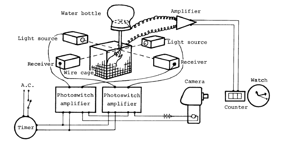
Figure 1. Yes, that is a camera triggered to take a picture of a counter and a watch whenever a mouse licks for water. Pretty ingenious if you ask me!
The basic idea is still the same today: use some sort of sensor to detect when a rodent licks for water. The Murakami study above was interested in measuring circadian rhythms. They used the lick sensor 24 hours a day to see if it could reveal the mouse’s circadian rhythm. It did! The mice in this study licked slower during the “day/light cycle” and faster at “night” presumably because they are more active at night. Technically though, mice are “crepuscular,” meaning they are most active at sunrise and sunset.
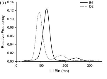
Figure 2. Different gifts for gab. C57BL/6 (B6) lick a bit slower than DBA/2 (D2). To go from Inter-lick intervals (ILI) in milliseconds to licks per second, you just take 1000ms divided by the peak values of those distributions (~119.5 ms and ~137.3ms).
Another fun mouse licking fact is that different genetic strains of mice lick at different speeds! Two common strains of mice used in medical research are C57BL/6J and DBA/2J mice. In a study performed in 2007, Boughter et al. found that the former lick about 7.3 times per second, while the latter lick at a zippy 8.4 times per second. I actually use C57BL/6 mice in my work, so the “B6” distribution will come in handy later as a good measure of comparison.
Edit: If you end up using the design described below, please consider citing the paper which led to its creation!
Building the Lickometer
Back To Top
So let’s make a lickometer. I decided to go with an infrared optical beam-break design to reduce electrical artifacts in our neural recording.
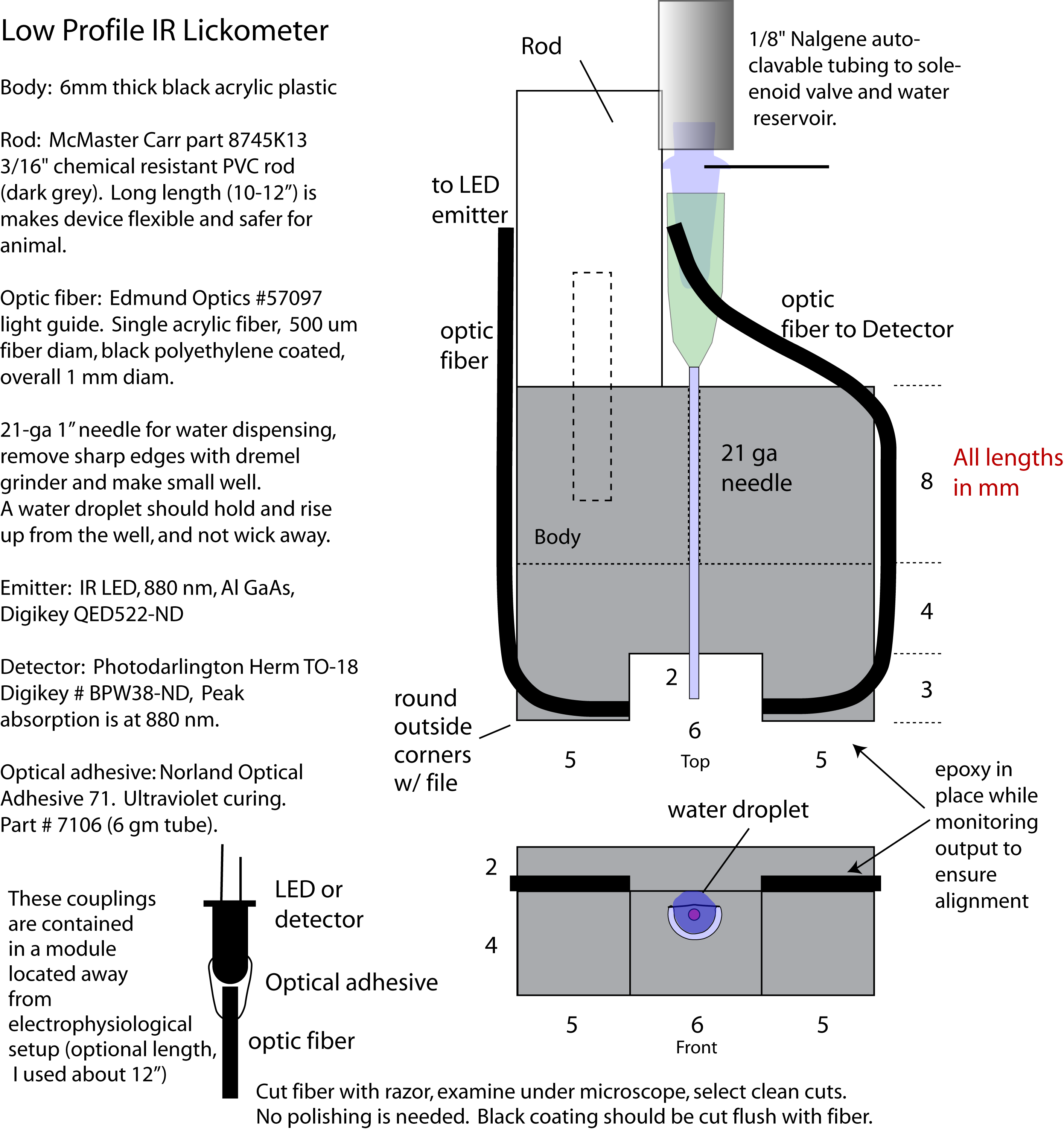
Since we did not want to obstruct the whiskers (we want the whiskers to touch shapes while the mouse is near the lickometer), I needed the lickometer as low-profile as possible. A parts list and general schematic is shown below.
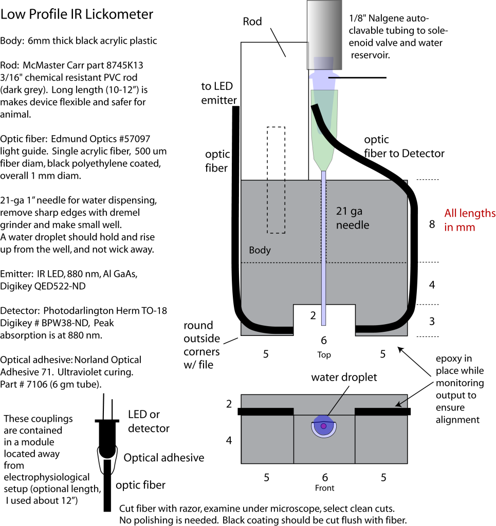
Figure 3. The physical construction and parts list of IR Lickometer
The rod of this device is held in a standard 3-axis manual micromanipulator so it can be positioned in the same exact position each day (for example, something like this).
The construction of this lickometer assumes familiarity with safe use of a Dremel, drill press and end mill. I machined the body of the lickometer from stock sheets of 6mm black acrylic plastic using a Sherline Endmill and a drill press for the through-hole of the water spout. If I were going to make a few of these in the future, I would probably just have the body piece 3D printed. The rear of the body and mating end of the rod are tapped for a small set screw (I think I used 4-40).
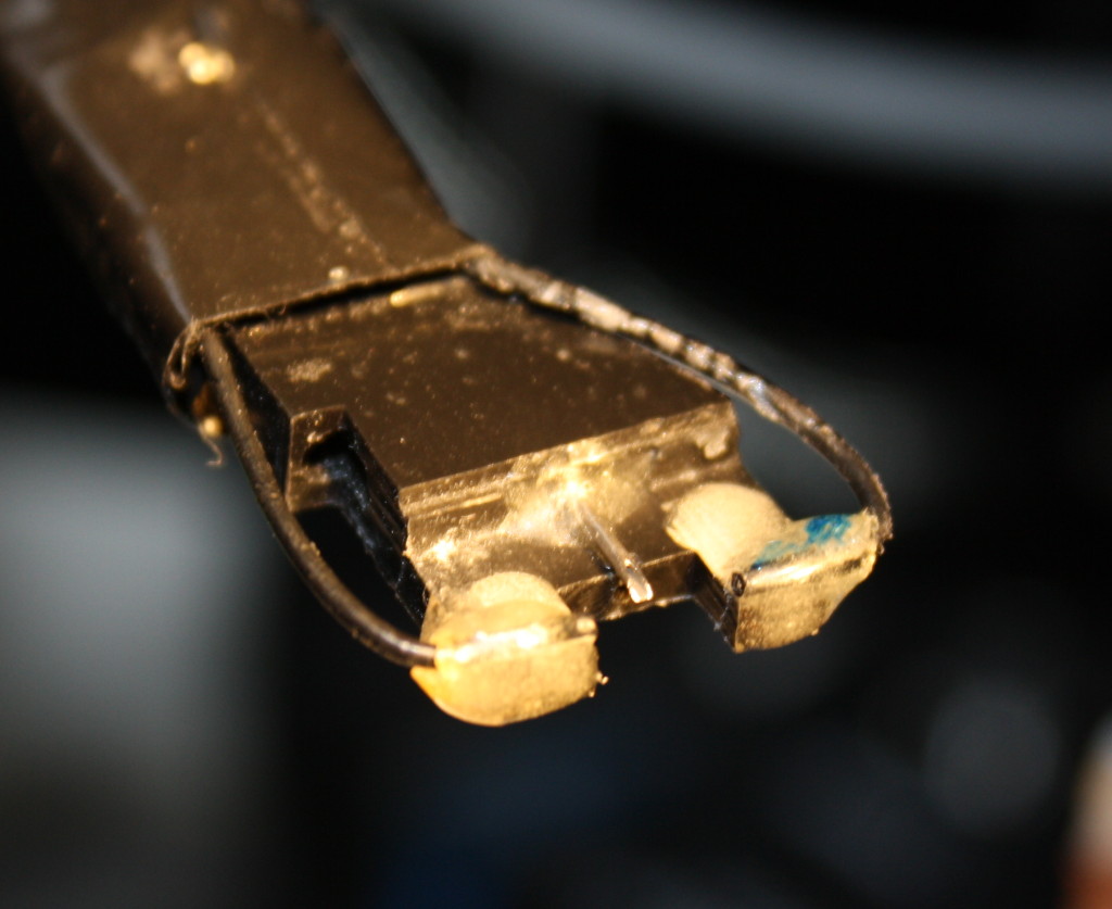
Figure 4. Bring on the licks!
The small fiber optic cables allow the the infrared beam to be precisely in front and above the water spout, yielding great lick detection. I simply used optical epoxy to attach one fiber optic to the IR LED and one to the IR detector respectively. The fiber optic cables are then held in place by Zap Z-poxy (the best all purpose epoxy in my opinion).
The water spout is made from a 21 gauge needle by Dremeling off the sharp edge and tip with a circular grit disk and leaving a longish square opening (sparks will fly, always use eye protection!). The water spout should be epoxied in place first.
Lickometer circuitry
Back To Top
In order of this device to be useful, we need clean signals of when the mouse is licking. Since I also want to trigger other events off the occurrence of a lick I decided to make a circuit that turns the licks into a pulse over 3.5V in order to be correctly interpreted by the digital inputs of an Arduino.
Since IR detectors actually produce an analog voltage that increases with IR light intensity, we also need to inverse the signal (the tongue blocks the beam, causing a shadow that we want to represent as a positive voltage signal). In the circuit below I take advantage of a nifty circuit component called an Inverting Schmitt trigger to achieve both of our goals. This circuit uses an opamp and some resistors to invert the signal and set two thresholds: one positive input threshold that will cause the output signal to saturate at a desired voltage (in my case, a +4v pulse) until a second threshold is crossed (on the way down). This second threshold allows the output to collapse back to a baseline voltage below 3.5V (1V in my case).
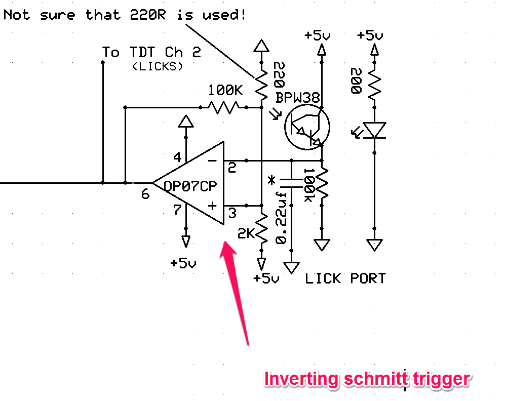
Figure 5. Circuitry that connects to the IR LED and IR detector and produces a digital pulse when the IR detector is obstructed.
This circuit turns a wobbly dip in voltage from the analog output of the BPW38 IR detector into a nice clean digital pulse. The schmitt trigger can be tuned by changing resistor values. Note that the values shown above are for the complete build with attached fiber optic cables and will likely not work if you simply point the IR LED directly at the IR Detector. The resistors used above set the schmitt trigger for lower voltage due lower light levels with the fiber optic aperture. See the schmitt trigger calculator linked above for guidance on how to modify the circuit to your needs.
Lickometer in action
Back To Top
Here’s some early output from the lickometer while being licked:
Figure 6. Slurp slurp slurp.
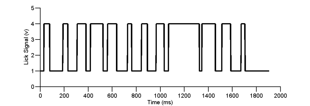
Each pulse has sharp onsets and offset allowing us to cleanly resolve when the sensor is blocked. The output shows pulses of different durations, which either means the tongue blocks the sensor for different amounts of time, or the sensor is faulty. A good way to check that we are in the right ballpark is to look at the inter-lick interval histogram! I mentioned above that it is known that C57BL/6 mice lick at around 7Hz, so I should see a clear peak around 130-140ms.
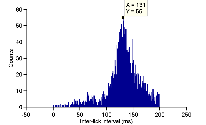
Here we clearly see a peak at around 131ms leaving an average lick rate for this mouse of ~7.6 licks / second. This is very close to the reported 7.2 Hz, and is likely within the variation expected from individual mice.
Above I’ve posted a video of a real-time program I wrote in MATLAB which plots the lickometer pulses in time (top row). An Arduino is also approximating an instantaneous lickrate plotted on the bottom row. In this example, every time the rate goes above the red dashed line, the animal gets a reward. The lick rate must then fall below the blue dashed line before the animal can trigger another reward. This is the early training we use to teach mice to start and stop licking. The middle row is the running speed of the mouse.
Well that Just about does it for an overview on the lickometer itself! Hopefully this inspires some other designs. I saw over on Labrigger that there are some simplified IR LED / Detector pairs from Omron that might simplify the lickometer construction. I will have another post soon about controlling and calibrating the solenoid valve in order to deliver very precise amounts of water (1-3 microliters!).
Edit 1: Calibrating the solenoid post is up here!
Edit 2: I also want to mention that the photobeam-break type lick port that I described above is only one of many designs. I have heard from several people who have successfully implemented capacitive lick sensors as well. My sense is that artifacts are a little bit harder to get rid of with capacitive sensors, but this can be a problem with either type of device, depending on grounding.
Thanks Lex! Hope it gives people some useful tips/ideas.
Hi Brian,
Great post! Just two questions, how long were your trials and did you provide any cue to initiate the start/end of a trial?
Thanks,
Christian
Hi Christian,
Sorry for the delayed response (busy couple of months over here)! Our trials are self-initiated so they vary in duration (the task is a “virtual foraging task”). That being said, we use a 1-2 second response window once the trial is initiated. And yes there are two tactile cues that a trial is in progress: 1st is that, after randomizing, the stimulus wheel returns to the whisker field (in a neutral, non-stimulus position). 2nd, when he animal has not licked in a few seconds, the mouse running wheel is allowed to control the movement of the stimulus wheel. When the animal has run a short distance, the stimulus enters the whisker field and the response window opens. This movement is noticeable to the animal prior to the stimulus entering the whisker field, so it is a cue that a trial is in progress. Hope that helps!
-Brian
Hi Brian,
Your design is incredibly helpful but I was wondering whether use of it has allowed you to refine your design. Specifically, have you confirmed whether or not the circuit actually contains a 200k resistor or whether something different should be used?
Hello! We are hoping to build 2 or 3-choice lickometers for mouse home cages to reduce the stress of transferring animals between their home cages and lickometry cages. Do you have a list of materials you used for this experiment? Do you measure volume of liquid or mostly the amount of licks?
Hi Barbara, if you are still interested, I just sent an e-mail followup that I hope reaches you well. -Brian