During my thesis I built a 1D virtual track that responded to mouse locomotion in order to naturalistically deliver tactile shapes and textures in a controlled environment:
The heart of this technical challenge was building the right running disk. In this post we will discuss how to make a low-weight running disk with high-speed, high-resolution positional readout. Along the way I discuss rotary encoders, quadrature, coding interrupts, and real-time responsive environments like the stimulus wall responding to mouse running shown above.
Edit: And if you end up using the design described below, please consider citing the paper which led to its creation!
- Introduction: running rodents
- Constructing a running disk
- Wiring the encoder
- What is quadrature?
- Decoding quadrature on an Arduino Uno
- Need for speed: closed-loop control
1. Introduction: running rodents
When a rodent explores its environment, it increases sensory information acquisition, and this facilitates primary cortical areas like visual cortex (Niell & Stryker 2010). In the case of the whisker system, it is well known that whisking frequency is highly correlated with running speed (Fig. 1).
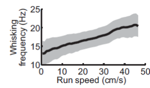
Fig. 1. Whisking frequency increases with running speed (From: Sofroniew et al. 2014).
In other words, rodents increase the acquisition rate of tactile information as they increase their running speed. This might be a byproduct of increased breathing rate, or it may be a way of making sure a lot of surrounding areas are still sampled by the whiskers at high running speeds. In either case: it’s pretty cool! Since so many behaviors are synchronized with running, it is often useful to allow rodents to run during experiments. And it’s even better if this running information can be used to gather position and velocity estimates for analysis and even “closed-loop” systems (more on that later).
Many scientists have implemented strategies for keeping track of rodent running speed and position, including the infamous(e) “Tank Ball” named after Professor David Tank at Princeton (a version of which is featured in this glorious Wired article). A Tank Ball consists of a Styrofoam ball floating on air (think ping-pong ball trick for scientists) with a computer optical mouse on one or two sides for reading ball movements.

Fig. 2. Tank Ball.
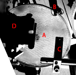
While this works great for visual stimuli (as shown above), we had concerns that the air blowing around could interfere with mouse whiskers in their normal movements. They are very fine hairs, and this could introduce unpredictable movements. Thus we settled on a simpler design: a 1D running wheel made of a 6″ plastic disk on a rotary encoder.
2. Constructing a running disk
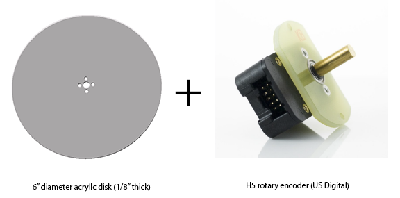
Fig 3. 1D running with a flat disk and a rotary encoder (H5-1000-IE-S, US Digital)
The disk can easily be laser-cut from an online company like Ponoko, or you can do what I did and make it yourself using a Dremel circle-cutter and a drill press (be sure you are trained in using these tools before any such effort!). However, you aren’t done yet: acrylic is too slippery for mice feet, so you will need to add a nice texture. I found attaching a fine polypropylene mesh (McMaster Carr) via epoxy at the edges provided a good solution. As for attaching the disk and encoder, we ordered encoders with precision ground 1/4″ shafts, so I found a matching 1/4″ hub and used a small set-screw for mounting to prevent imbalance (i.e. avoid a large machine screw hanging off the side). The hub I originally used isn’t available but this hub (Sparkfun) should work. Other good resources for these items are: Pololu, ServoCity. The wheel up to this point is shown in Fig. 4.
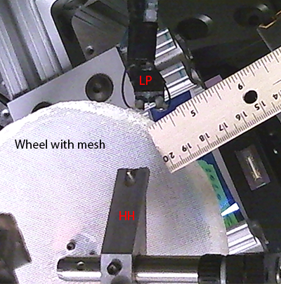
Fig. 4. Wheel with mesh attached to rotary encoder under lickport (LP) and head-holder (HH). Ruler for scale.
I later epoxied a thin 1/4″ plastic lip around the edge of the wheel to further aid traction (Fig. 5).
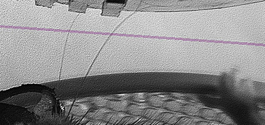
Fig. 5. 1/4″ lip made of shim plastic (held by mouse in picture). As shown, prevents mice feet from going off the edge of the wheel.
But constructing the wheel is really only half the battle, the next section will describe how we interpret information coming from a running disk / 1D track.
3. Wiring the encoder
Back to top
First thing is to wire up the encoder as per the datasheet. This will depend on whether your encoder is single-ended (one ground) or has differential output (two pins for each output–> this can be converted to single-ended). I used a single-ended encoder with 1000 pulses per rotation, with A and B outputs for quadrature (H5-1000-IE-S, US Digital).
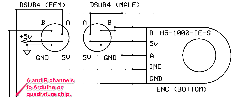
Fig. 6. Rotary encoder connected to a DSUB4-type connector.
In this configuration, we do not need the indexing pin (which can give an absolute reference pulse, once per rotation). If we want to know when the wheel moves forward vs. backwards, we need to interpret the quadrature. One possibility is to use a chip like the LS7184 chip to do this, but I found it was simpler to implement a real-time quadrature decoder on an Arduino, which I will describe below.
4. What is quadrature?
Back to top
Let’s first take a second to describe what signals a rotary encoder provides!
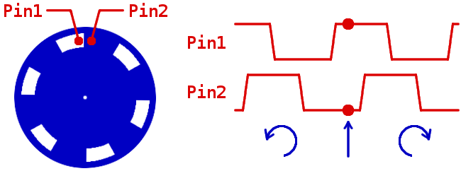
Fig. 7. Optical encoder creating quadrature clock. (Click to see source page of image).
Inside an optical encoder, you will find a very finely-marked transparent piece of plastic (symbolized by blue disk in Fig 7). By reading light occlusion from two neighboring sensors, different phases of light/dark will occur depending on whether the wheel moves clockwise or counter-clockwise (imagine starting from the arrow and reading left or right in Fig. 7). Thus, whenever either pin changes state, a known increment has occurred. To reveal the direction of this increment, we can check the state of the opposite pin of the pin that changed state. I phrased this in a particular way to make it more clear how we might write code, but to be clear: there are 4 possible states with particular transition paths and these can be used to create a state machine. If this all doesn’t quite make sense yet, draw out the possibilities and how to get to each state for yourself (if you are thorough, it should look something like this). Also, there are many good tutorials, including this one, which I adapted for the decoder described below.
5. Decoding quadrature on an Arduino Uno
Back to top
There are many ways to do this, but the one I liked most was to use 2 interrupt pins: one each for Channel A and B. Interrupt pins will momentarily leave whatever code is currently being processed and call a designated interrupt function. As I alluded to above, one way to implement this decoder would be: any time Channel A (B) changes state, call an interrupt and check the state of Channel B (A). Depending on the state of Channel B (A), increase or decrease a counter (or set a direction flag) as appropriate. Parenthetical letters are to show that we do this for when either channel A or B goes changes state.
To set up the interrupts on an Arduino Uno (there are only certain pins that operate this way), we do something like:
 #define chB  1      // Pin 3 is Int 1 on UNO
 #define chA  0      // Pin 2 is Int 0 on UNO
 volatile long clicks // Variable used to store wheel movements. Volatile is important
                      // for variables that can change in an interrupt
 void setup() {
   //This can be done here or at a relevant point in void loop().
   attachInterrupt(chA, quadA, CHANGE); // CHANGE = whenever input goes HIGH or LOW on chA, call function quadA
   attachInterrupt(chB, quadB, CHANGE); // And for chB
 }
A illustrative example of possible quadA and quadB functions would be something like this:
void quadA() {
  // If pin 2 (int 0) state CHANGES, this interrupt is called.
  if (digitalRead(chA)==HIGH) { //If this pin (DIO2) is HIGH
    //Check state of DI03:
    if (digitalRead(chB) == HIGH) { //if DI03 is high
      clicks++; // Wheel is turning backwards/clockwise (mouse running forwards)
    }
    else {
      clicks--; // Wheel is turning forwards / counter-clockwise (mouse "running" backwards):
    }
  }
  else { //IF DI02 is LOW
    //Check state of DI03:
    if (digitalRead(chB) == HIGH) { //if DIO3 is high
      clicks--; // Wheel is turning fowards
    }
    else {
      clicks++; // Wheel is turning backwards
    }
  }
}

void quadB() {
  // If pin 2 (int 0) state CHANGES, this interrupt is called.
  if (digitalRead(chB)==HIGH) { //If this pin (DIO3) is HIGH
    //Check state of DI02:
    if (digitalRead(chA) == HIGH) { //if DI02 is high
      clicks--; // Wheel is turning forwards / counter-clockwise (mouse "running" backwards):
    }
    else {
      clicks++; // Wheel is turning backwards/clockwise (mouse running forwards)
    }
  }
  else { //IF DI03 is LOW
    //Check state of DI02:
    if (digitalRead(chA) == HIGH) { //if DIO2 is high
      clicks++; // Wheel is turning backwards
    }
    else {
      clicks--; // Wheel is turning forwards
    }
  }
}
Two things become clear from this example: 1) Notice that the state (chA==HIGH, chB==HIGH) has opposite meaning depending on which pin changed. Thus, quadrature is largely about capturing transitions and not states themselves. The quadA() and quadB() functions are exactly inverted, as they capture complementary sets of transitions. 2) Quadrature gets 4x higher step resolution than the listed “Clicks Per Rotation” of the encoder (which is the pulse resolution of a single A or B channel by itself). In this case, the encoder is 1000 CPR, and I used quadrature to read 4000 CPR. Thus we can convert clicks into a real distance using 2*π*r / clicks, where r = mean radius of the mouse’s position on the running disk.
6. Need for speed: closed-loop control
Back to top
To prevent interrupts from disrupting your other Arduino code excessively, the interrupt functions need to be very fast. With higher encoder resolution, this becomes quite relevant, as higher CPR means more interrupts to handle. There are several ways to make interrupts faster:
1) Do little more than increment a counter / set pin states in the interrupt, and address the implications of these state changes outside of the interrupts
2) Use the digitalWrite2() package available here for any pin state manipulations within the interrupt.
3) For an extra boost, consider checking pin states using hardware-specific code as opposed to using the native digitalRead( ) function. The downside to this is that the hardware can no longer port between different Arduino types, so this is generally not recommended. But for my purposes, it ended up being necessary.
In addition to being fast, I wanted to use the same interrupts to optionally yoke the movement of a stepper motor to the incoming quadrature pulses, thus creating a closed-loop interface where mice ran in a 1D virtual track. The combination of these goals leads to a slightly more complex quadA() and quadB() function:
void quadA() {
  // If pin 2 (int 0) state CHANGES, this interrupt is called.
  if ((PIND & (1 << PIND2)) == 0) { //If this pin (DIO2) is HIGH
    //Check state of DI03:
    if ((PIND & (1 << PIND3)) == 0) { //if DI03 is high (c code digital read of DI03 on UNO )
      clicks++; // Wheel is turning backwards & set direction pin state;
      // Set direction pin state:
      digitalWrite2(stimWheelDir, HIGH); // PORTD |= (1<<PIND5); //HIG
    }
    else {
      clicks--; // Wheel is turning forwards & set direction pin state
      // Set direction pin state:
      digitalWrite2(stimWheelDir, LOW); //PORTD &= !(1<<PIND5);//
    }
  }
  else { //IF DI02 is LOW
    //Check state of DI03:
    if ((PIND & (1 << PIND3)) == 0) { //if DIO3 is high  (c code digital read of DI03 on UNO )
      clicks--; // Wheel is turning fowards
       // Set stepper motor direction pin state:
      digitalWrite2(stimWheelDir, LOW); //PORTD &= !(1<<PIND5);//
    }
    else {
      clicks++; // Wheel is turning backwards
      // Set stepper motor direction pin state:
      digitalWrite2(stimWheelDir, HIGH); // PORTD |= (1<<PIND5); //HIGH
    }
  }
  if (syncMove) {
    //Serial.println(clicks);
    digitalWrite2(stimWheelStp, HIGH); // but faster: PORTD |= (1<<PIND4); // (1<<PIND4); //Equivalent to digitalWrite2(stimWheelStp,HIGH); but faster
    delayMicroseconds(stepPulseDur);//
    digitalWrite2(stimWheelStp, LOW); // but faster: PORTD &= !(1<<PIND4); // Equivalent to
  }
}
void quadB() {
  // If pin 3 (int 1) state CHANGES, this interrupt is called.
  //If DI03 is HIGH
  if ((PIND & (1 << PIND3)) == 0) {
    //Check state of DI02:
    if ((PIND & (1 << PIND2)) == 0) { //if DI02 is high  (c code digital read of DIO2 on UNO)
      clicks--; // Wheel is turning forwards
      // Set direction pin state:
      //Pin 5
      digitalWrite2(stimWheelDir, LOW); //PORTD &= !(1<<PIND5);//
    }
    else {
      clicks++; // Wheel is turning backwards
       // Set stepper motor direction pin state:
      digitalWrite2(stimWheelDir, HIGH); // PORTD |= (1<<PIND5); //HIGH
    }
  }
  else { //IF pin B is LOW
    if ((PIND & (1 << PIND2)) == 0) { //if DI02 is high  (c code digital read of DIO2 on UNO)
      clicks++; // Wheel is turning backwards
      // Set direction pin state:
      digitalWrite2(stimWheelDir, HIGH); // PORTD |= (1<<PIND5); //HIGH
    }
    else {
      clicks--; // Wheel is turning forwards
       // Set stepper motor direction pin state:
      digitalWrite2(stimWheelDir, LOW); //PORTD &= !(1<<PIND5);//
    }
  }
  if (syncMove) {
    digitalWrite2(stimWheelStp, HIGH); // but faster: PORTD |= (1<<PIND4); // (1<<PIND4); //Equivalent to digitalWriteFast(stimWheelStp,HIGH); but faster
    delayMicroseconds(1);//
    digitalWrite2(stimWheelStp, LOW); // but faster: PORTD &= !(1<<PIND4); // Equivalent to
  }
}
Which leads to closed-loop behavior like this:
That’s about it for running disks! In the future this post will be paired with stepper motor stimulus control…
Hello!
Great post and thank you for sharing!
Inspired by it, at our lab we’d like to use an encoder with an horizontally-placed acrylic disc for measuring locomotion. However, our encoder, the Avago HEDS-5500, needs to have its lower “plate” fixated to a surface, usually a motor, while the shaft goes inside it from one side (and does not come away on the other).
https://media.digikey.com/Photos/Broadcom/HEDS-5500%23A12.jpg
Is there a set-up that you could recommend for that?
I’m very glad it was helpful! I’m sure you’ve found a good solution by now — I’m sorry that this comment did not trigger an alert so went unnoticed. If I understand correctly your encoder passes the shaft through the enclosure ? I would buy a small segment of precision ground shaft exact size of encoder to mount acrylic disk to your current encoder then drill and thread a small hole on the cable side to allow mounting encoder to rigid beam. Let me know how you solved it! I’m curious to hear!