- Introduction
- Tubing up the solenoid
- Solenoid driver circuitry
- Calibrating volume delivery
- Arduino code example
1. Introduction
In a previous post, I described how to build an infrared lickometer (lick detector), but have yet to describe how to calibrate and deliver water from such a device. (Shout out to Allan-Herman Pool at Caltech for the encouragement to finish the story here!).
Edit: If you do end up using this design, please consider citing the paper which led to its creation!
2. Passive dispenser, tubing logic
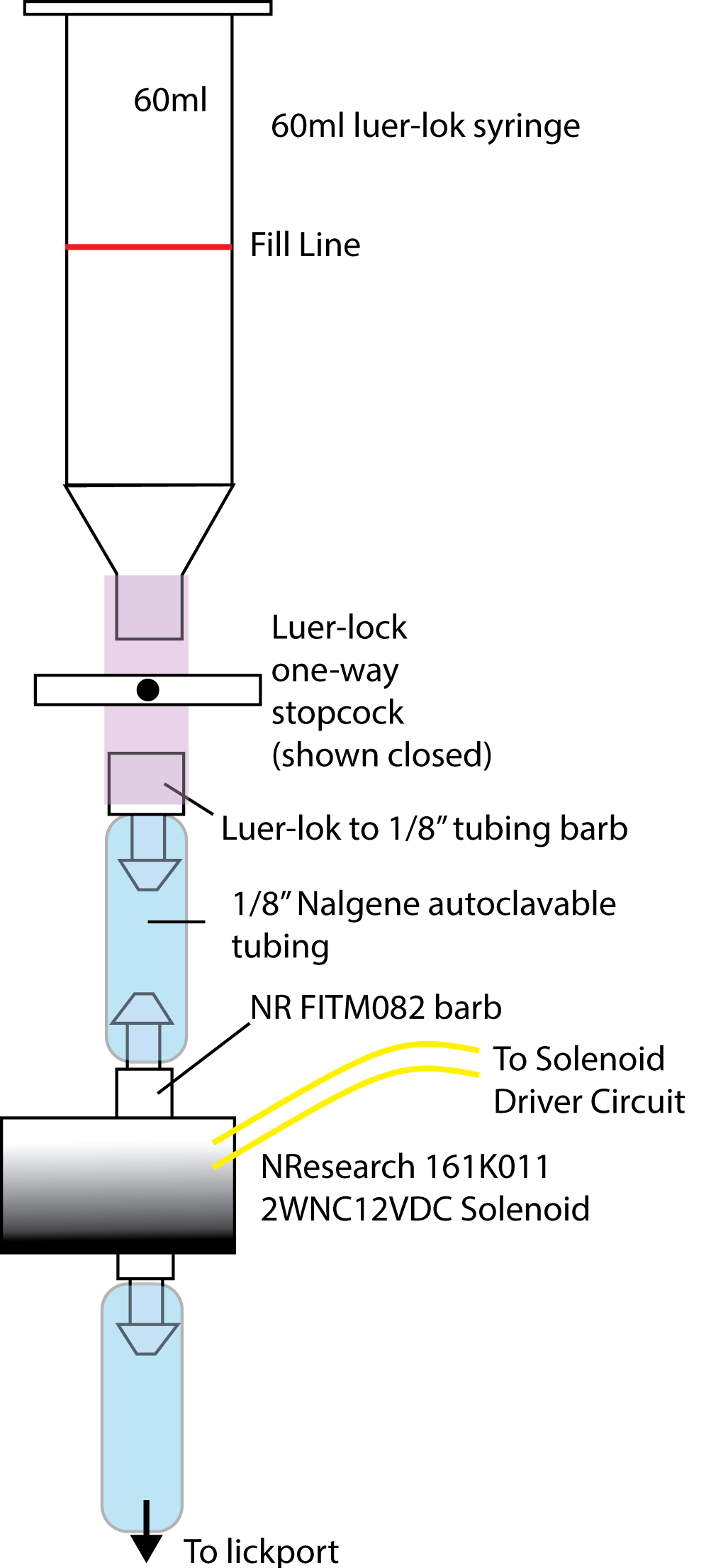
The idea for passive dispensors is to use gravity as the driving force for our water delivery system. We gate the flow of water using a “Normally Closed” solenoid, which we drive open for certain amounts of time using a simple circuit (described below). The longer we open the solenoid, the more water flows through! Since I am interested in delivering very small amounts of water (1-4ul), the solenoid needs to be able to open and close in 10s of milliseconds.
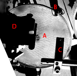
Figure 1 shows the basic logic of how to set up a water reservoir using a 60ml syringe, and a solenoid. I include a manual way to close off the water flow (the one-way stopcock). This comes is handy if you need to disconnect the rest of the tubing for any reason, or if the solenoid starts misbehaving (to stop water from going everywhere).
3. The solenoid driver circuit
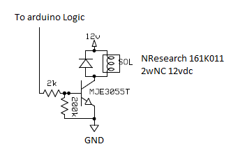
To open and close the solenoid valve, we rely on a high-current NPN transistor (MJE3055T). Now, by giving a 5V pulse from a digital logic device, in this case an Arduino Leonardo, we can trigger the transistor to allow current to flow through our solenoid from a 12V power source. Since we have a Normally Closed solenoid, driving the solenoid will allow it to open (it will close passively when no current flows through). This type of circuit is actually useful whenever we want to gate a component that requires current or voltage higher than our logic device can provide (40mA at 5V, in the case of an Arduino).
Now, by changing the duration of our logic pulse, we can change the amount of time the solenoid stays open. With longer pulses, we allow more water to flow through. One thing to note is that different solenoids have different “duty cycles”– this means that not all solenoids are designed to be driven for long amounts of time without also taking a break for some amount of time (opening for 30% of the time and resting 70% of the time would be a “30% duty cycle”). Therefore, it’s worth looking up the recommended duty cycle to avoid driving the solenoid in ways that will potential cause the device to overheat and stop performing correctly.
Another thing to note is the diode in parallel with the solenoid–this is called a “flyback” diode, which you can find more details about here. It essentially protects the rest of your circuit from a voltage spike caused by the magnetic field inside the solenoid collapsing when the solenoid turns off (more info here!).
4. Calibrating the lickport

Now we have everything we need to make a successful lickport! The only thing left to do is calibrate the system.
There are two key factors for calibrating the lickport:
1) The duration of time the solenoid opens per click, and
2) The height of the water reservoir above the lickport opening.
It is very important that you calibrate the system in the exact configuration that you will use! Changing the height of the water reservoir will change the driving force, and thus the flow-rate. For the same reason, it is important to keep the water reservoir at a consistent volume (hence the “fill-line” in Figure 1). Keeping the water at the level you calibrate will make the system very accurate. Using a large reservoir like the one shown (60ml) also has the advantage of minimizing this volume change / change in driving force over the course of a training session.
I’m sure there are many ways to perform the actual calibration but if you have access to a scale that measures down to micrograms (many laboratories will have one), by far the easiest way is to simply find the relationship between solenoid open duration and water output volume. Even if you have a less precise scale, the same method is possible, (it just might take longer ;-).
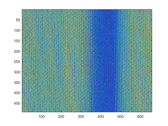
To find the relationship in Figure 3, I open the solenoid 50-100 times at several different durations and collect the resulting volume of water in centrifuge testubes for each duration. Since 1 microliter weighs 1 microgram, we can divide the weight of this volume by the number of times the solenoid opened at a given duration. After doing this for several open durations, I fit a line to the relationship. Now when I run my training, I can input the volume of water I wish to deliver per reward and automatically use the correct open duration for the solenoid! Pretty simple, but it works great. If you have a less precise scale, you will need to open the solenoid enough times to get a volume in the regime of your scale precision. Note: be sure to open the solenoid enough times to remove all air bubbles from the tubing before you start.
As for the height of the reservoir, I use a height of about 10cm above the level of the lickport (yielding the relationship shown in figure 3). Note: in theory it doesn’t matter too much what the tubing between the reservoir and lickport does (it could go up ten feet and back down ten feet). All those forces should cancel out, conserving the driving force as just the height of the reservoir above the lickport. This can be useful to keep in mind as it allows you some flexibility in how to arrange the tubing.
5. Arduino code example of calibration
Back To Top
Below, I’ve written a very basic Arduino routine that will allow you to open the solenoid many times at a fairly accurate duration for one run of the calibration described above.
/* solenoid_calibration_routine Takes an integer number of milliseconds from the Serial Monitor and clicks a solenoid 100 times at that millisecond duration. Note: Serial monitor must have Newline character and 9600 Baud selected to work correctly. Brian Isett, 2016-06-19 */ const int solenoidPin = 13; // change this to the pin connected to the solenoid driver circuit, //pin 13 will flash the onboard Arduino Uno LED const int offDuration = 500; // Value in ms to wait in-between solenoid openings (you might need to adjust this) int openDuration = 0; const int numClicks = 100; // Number of solenoid clicks to deliver during one "open duration" calibration run void setup() { // set the digital pin as output: pinMode(solenoidPin, OUTPUT); Serial.begin(9600); // For our example, lets us type in a duration into the Serial Monitor Serial.println("Ready!"); } void loop() { //Read in a value input typed into the Arduino IDE Serial Monitor as an open duration (in milliseconds). if (Serial.available() > 0){ openDuration=Serial.parseInt(); //Make sure 'Newline' is enabled in your serial monitor! }else{ openDuration=0; } if (openDuration > 0) { Serial.print("Using "); Serial.print(openDuration); Serial.println("ms solenoid open duration"); for (int i=0; i < numClicks;i++) { digitalWrite(solenoidPin,HIGH); delay(openDuration); digitalWrite(solenoidPin,LOW); delay(offDuration); } Serial.print("Delivered "); Serial.print(numClicks); Serial.println(" solenoid clicks."); } } |